Reliability~
Reliability is Important for a company~
It is defined as the ability of a device to conform to its electrical and visual/mechanical specifications over a specified period of time under specified conditions at a specified confidence level
At the same time, It may represent a reputation of a company~
Hence,for the device a company develop and produce...For sure few reliability test will be done on it for the purpose of measuring the quality of bonds~~
What types of reliability test will be done a small chips??
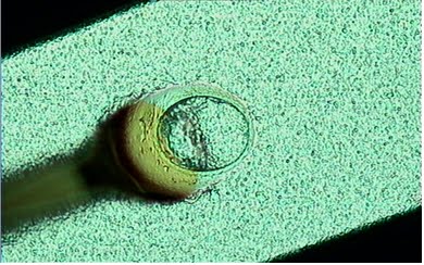
- Visual Inspection
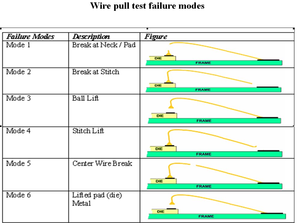
- Bond pull
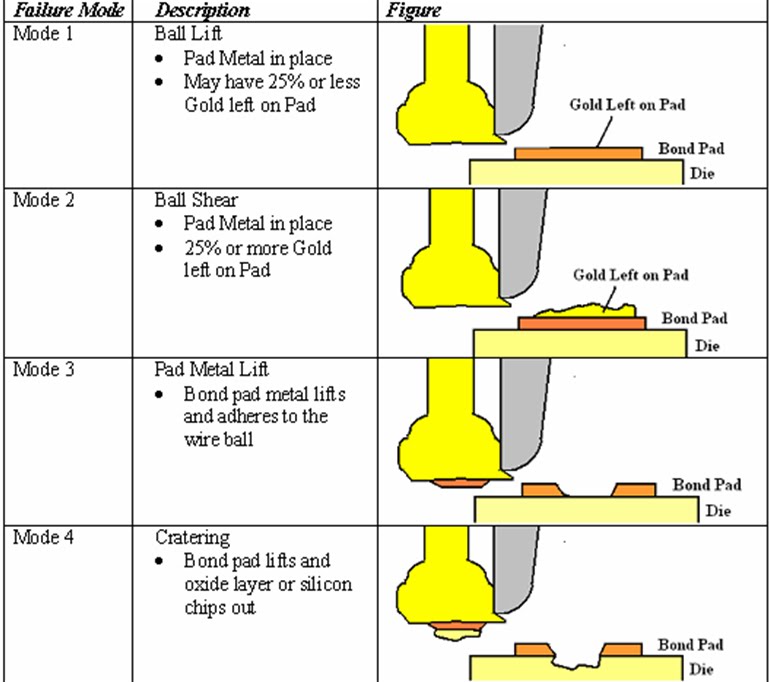
- Bond Shear Test
- Bond Etching
- Electrical Testing
- Bake Test
- Thermal Cycle/Thermal Shock Testing
- Autoclave Testing
- Surface Anaylisis
- Temperature, Huminity, Bias (HTB)
**Some of this tests are usable as production monitoring techniques, where as some tests can only be used in the laboratory for evaluation and development of wire bond technology.
Reliability is Important for a company~
It is defined as the ability of a device to conform to its electrical and visual/mechanical specifications over a specified period of time under specified conditions at a specified confidence level
At the same time, It may represent a reputation of a company~
Hence,for the device a company develop and produce...For sure few reliability test will be done on it for the purpose of measuring the quality of bonds~~
What types of reliability test will be done a small chips??
- Visual Inspection
- Bond pull
- Bond Shear Test
- Bond Etching
- Electrical Testing
- Bake Test
- Thermal Cycle/Thermal Shock Testing
- Autoclave Testing
- Surface Anaylisis
- Temperature, Huminity, Bias (HTB)
**Some of this tests are usable as production monitoring techniques, where as some tests can only be used in the laboratory for evaluation and development of wire bond technology.
![]()


 THE END ~HIsOmET~!


